Fire emergency lighting is suitable for fire emergency lighting, is the most common lighting tool in fire emergency, emergency time is long, high brightness has automatic emergency function.The fire emergency lamp has the characteristics of low power consumption, high brightness, long service life and so on. The edge is designed with power switch and indicator light, suitable for factories, hotels, schools, units and other public places for emergency lighting in case of power failure.The quality of fire emergency lamp is related to life safety, and its function and lighting time are important indicators in critical moments.
This time we will disassemble a fire emergency lighting:

1.Disassembly preparation:
(1)Prepare materials and tools
(2)Fire emergency light 1 pcs
(3)Screwdriver 1 pcs
(4)Other tools, etc
2.Main panel inspection:
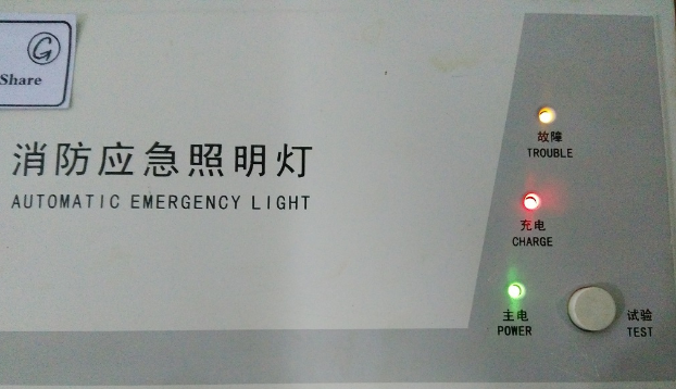
There are three indicators on the front panel: fault indicator, charging indicator and main power indicator, as well as an experimental touch switch button, the role of the button is to simulate the power failure when pressed in the case of main power, check whether the emergency lamp lighting function is normal. When the power is connected, the fault light is normally off, but now the three indicators are on, which indicates that the internal circuit is faulty and cannot be used normally, and further maintenance is required.
3.Disassemble internal circuits:
The next step is to disassemble the internal circuit, remove the screws at the bottom first, remove a total of four screws up and down to open the shell. There are blackened marks on the interior top of the shell, and it remains to be further checked whether any components are burned.
The blackened position is just above the transformer, but the transformer function is normal and no damage is detected. The source of the blackened material is unknown, which is very interesting to think about. Unplug the connector of the indicator key module and see all the internal structure: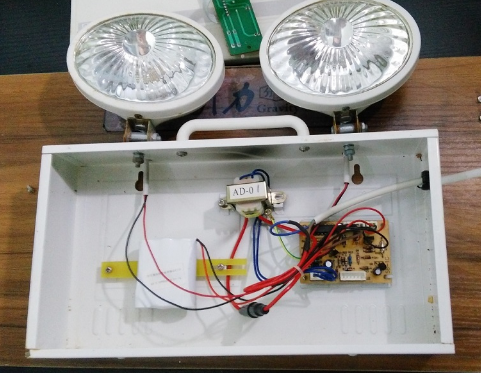
4. Detection components:
The main circuit board, because of the single-side printing process, the top layer is all disassembled components, and the bottom layer has some patch components, among which the delay switch chip adopts CD4541BE: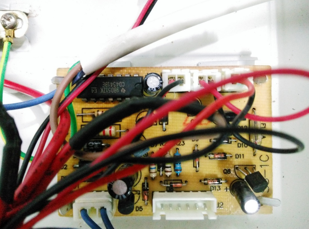
Underlying printed circuits and patch components: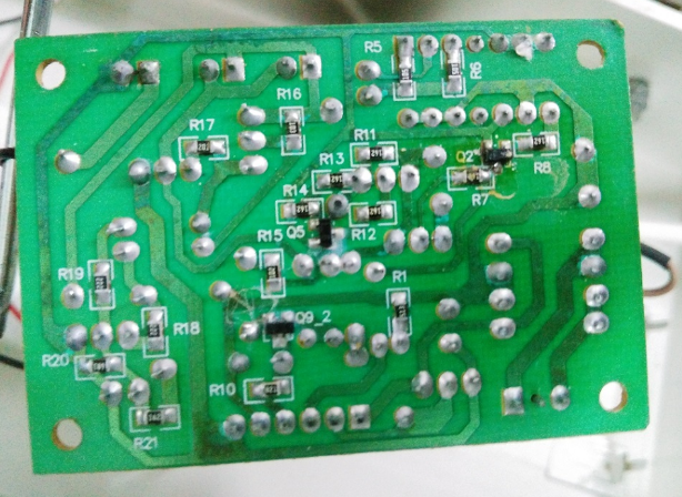
5.Disassemble the light:
After dismantling the internal structure to see the next two floodlights, lampshade screw in the lower part, the connection has the trace of rust, screw off the screw can open lampshade.
The lamp set is composed of several parts: the fixed ring of the glass cover, is metal material, glass lampshade, due to the effect of the above grain, the scattering effect of the lampshade is good, reflective cover and wick, 7 LED lamp set composed of beads, the circuit board of the LED lamp set back, fixed by two screws to the reflective cover: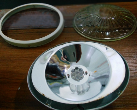
6.Disassembly principle analysis:
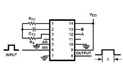
The core element of this fire emergency light delay power off switch is THE CD4541BE, which is a CMOS programmable oscillating frequency divider with adjustable timing and 14-pin package. By changing the combination of programming control level connected to pin 12 and 13, the subsequent delay series of built-in oscillation and counter can be adjusted in different grades, and the desired output timing range can be selected. It can be functionally controlled by changing the level of pin 5, 6, 9 and 10.
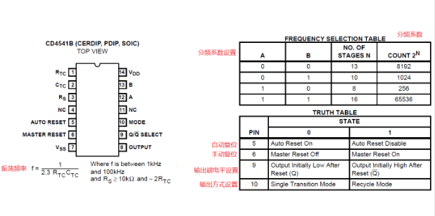 The following is the application circuit of the chip. At least three peripheral components are needed to realize the design of the delay switching circuit. The corresponding parameters can be set by designing the high and low levels of the pins: